
When we use a computer, open a website, send a file, watch a video, or communicate with another device on a local network, enormous amounts of data move between devices within milliseconds.
But what actually travels through an Ethernet cable?
Does the cable carry a packet, a frame, or raw data?
What is a MAC address?
How does a switch know where to send an Ethernet frame?
What is a MAC address table?
Where do IPv4 and IPv6 packets fit inside an Ethernet frame?
And what are Preamble, SFD, EtherType, Payload, and FCS?
To understand VLANs, switching, routing, VXLAN, network security, and even packet analysis, we first need to understand Ethernet at the frame level.
This article explains Ethernet from the ground up.
Table of Contents
1. What Is Ethernet?
Ethernet is a family of networking technologies and standards used primarily for communication over wired local-area networks (LANs).
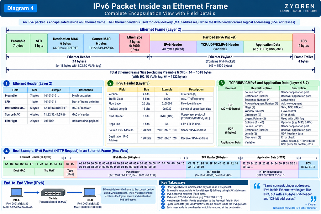
In simple terms:
Ethernet defines how devices communicate over a local wired network at the Data Link and Physical layers.
A simple Ethernet network may look like this:
PC-A
  │
  │ Ethernet Cable
  │
  ▼
Switch
  │
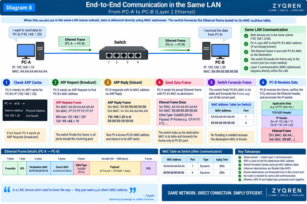
  │ Ethernet Cable
  │
  ▼
PC-B
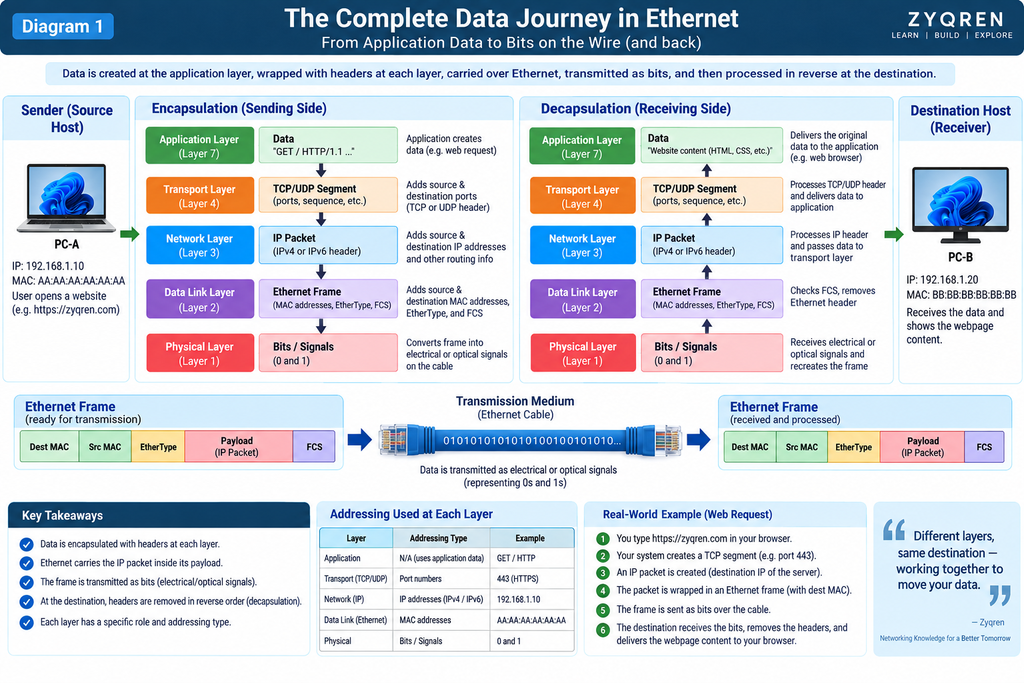
When PC-A sends data to PC-B, the application does not directly put its data onto the cable.
The data passes through multiple networking layers.
Conceptually:
Application Data
       ↓
TCP / UDP
       ↓
IP Packet
       ↓
Ethernet Frame
       ↓
Physical Signals
       ↓
Ethernet Cable
This process is called encapsulation.
2. The Most Important Question: What Actually Moves?
One of the most common networking confusions is using the words data, packet, and frame interchangeably.
They are related, but they are not the same thing.
Consider this simplified hierarchy:
Application
     │
     ▼
Application Data
     │
     ▼
TCP/UDP Segment or Datagram
     │
     ▼
IP Packet
     │
     ▼
Ethernet Frame
     │
     ▼
Bits / Physical Signals
Each layer adds information required by that layer.
For example, an application may generate:
"Hello Server"
TCP adds transport information.
IP adds source and destination IP addresses.
Ethernet adds source and destination MAC addresses.
The result is an Ethernet frame that can travel across the local network.
3. Encapsulation — How Data Gets Wrapped
Imagine sending a parcel.
You have:
Actual item
   ↓
Box
   ↓
Shipping label
   ↓
Transport vehicle
Networking works in a similar way.
Suppose an application wants to send:
Hello
The data moves down the protocol stack.
Step 1 — Application Data
Hello
Step 2 — Transport Layer
TCP or UDP adds its header.
TCP Header
+
Application Data
This creates a TCP segment.
Step 3 — Network Layer
IPv4 or IPv6 adds an IP header.
IP Header
+
TCP Header
+
Application Data
This is an IP packet.
Step 4 — Ethernet
It adds its Layer-2 information.
Ethernet Header
+
IP Packet
+
FCS
Now we have an Ethernet frame.
Conceptually:
┌───────────────────────────────────────────────┐
│ Ethernet Header                               │
│                                               │
│  Dest MAC │ Src MAC │ EtherType              │
├───────────────────────────────────────────────┤
│ IP Header                                     │
├───────────────────────────────────────────────┤
│ TCP/UDP Header                                │
├───────────────────────────────────────────────┤
│ Application Data                              │
├───────────────────────────────────────────────┤
│ FCS                                           │
└───────────────────────────────────────────────┘
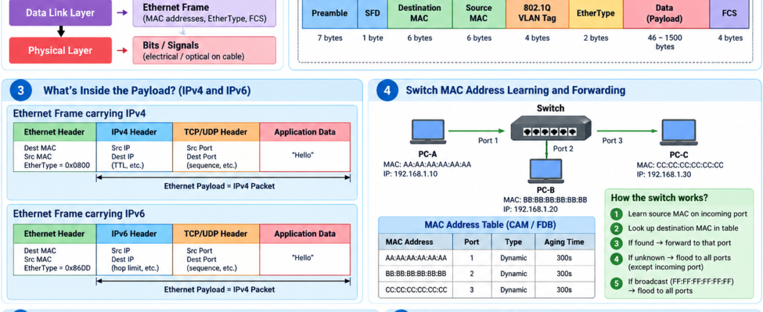
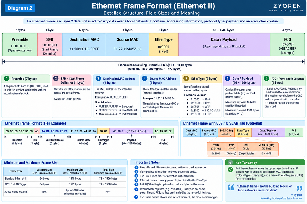
4. Ethernet Frame — The Basic Unit
At the Ethernet Layer-2 level, the fundamental data unit is called a frame.
A simplified Ethernet frame can be represented as:
┌──────────┬─────┬──────────┬──────────┬──────────┬────────────┬─────┐
│ Preamble │ SFD │ Dest MAC │ Src MAC  │ 802.1Q   │ EtherType  │Data │
│          │     │          │          │ (optional)│           │     │
└──────────┴─────┴──────────┴──────────┴──────────┴────────────┴─────┘
                                                                     │
                                                                     ▼
                                                                    FCS
For a normal untagged Ethernet II frame, the important fields are:
Preamble
SFD
Destination MAC
Source MAC
EtherType
Payload
FCS
An 802.1Q VLAN tag can be inserted between the Source MAC and EtherType.
5. Preamble — Getting the Receiver Ready
The Preamble is used at the beginning of an Ethernet frame to help the receiver synchronize with the incoming transmission.
It is 7 bytes long.
Conceptually:
10101010 10101010 10101010 ...
It provides a known pattern that helps the receiving Ethernet interface establish timing/synchronization for the incoming frame.
Think of it as:
“A frame is about to arrive; get synchronized.”
6. SFD — Start Frame Delimiter
After the Preamble comes the:
SFD = Start Frame Delimiter
It is 1 byte.
Its purpose is to indicate:
“The actual Ethernet frame starts after this point.”
So:
Preamble
   ↓
SFD
   ↓
Destination MAC
The Preamble helps synchronization, while the SFD marks the boundary where the frame begins.
7. Destination MAC Address
The first major address field in the Ethernet frame is the:
Destination MAC Address
Example:
AA:BB:CC:DD:EE:FF
It tells the local Ethernet network which interface the frame is intended for.
Example:
PC-A
MAC = 00:11:22:33:44:55

       ↓ Ethernet Frame

Destination MAC =
AA:BB:CC:DD:EE:FF

       ↓

PC-B
MAC = AA:BB:CC:DD:EE:FF
The Ethernet switch uses the destination MAC address to determine where the frame should be forwarded.
8. Source MAC Address
The next field is the:
Source MAC Address
It identifies the Ethernet interface that originated the frame.
Example:
Source MAC:
00:11:22:33:44:55
A frame may therefore look like:
Destination MAC:
AA:BB:CC:DD:EE:FF

Source MAC:
00:11:22:33:44:55
In simple terms:
Source → Destination
9. What Is a MAC Address?
MAC stands for:
Media Access Control
A MAC address is a Layer-2 address associated with a network interface.
A common representation is:
00:11:22:33:44:55
It is normally represented as a 48-bit value.
That means:
48 bits
=
6 bytes
=
12 hexadecimal digits
Example:
00 : 11 : 22 : 33 : 44 : 55
 \_________________________/
          48 bits
However, it is important to understand that MAC addressing is not simply “the permanent physical identity of a device.”
Modern operating systems and network interfaces can use locally administered MAC addresses, and virtualization, containers, and other technologies can create or assign MAC addresses.
The important networking concept is:
It uses MAC addresses for Layer-2 frame delivery.
10. EtherType — What Is Inside the Frame?
After the Source MAC comes the EtherType field in an Ethernet II frame.
EtherType tells the receiver what protocol is carried inside the Ethernet payload.
Common examples include:
0x0800  → IPv4
0x86DD  → IPv6
0x0806  → ARP
Therefore, if a frame contains an IPv4 packet:
EtherType = 0x0800
If it contains an IPv6 packet:
EtherType = 0x86DD
This allows the receiving system to know how to interpret the payload.
11. Payload — Where the Actual Upper-Layer Data Lives
The Ethernet frame carries a payload.
For example, when It is carrying IPv4:
Ethernet Frame
┌─────────────────────────────┐
│ Destination MAC             │
│ Source MAC                  │
│ EtherType = IPv4            │
├─────────────────────────────┤
│                             │
│       IPv4 Packet           │
│                             │
│   IPv4 Header               │
│   TCP/UDP Header            │
│   Application Data          │
│                             │
└─────────────────────────────┘
So the Ethernet payload is not necessarily “the user’s data.”
It can contain another protocol’s packet.
For example:
Ethernet Payload
      ↓
IPv4 Packet
      ↓
TCP Segment
      ↓
HTTP Data
This distinction is extremely important.
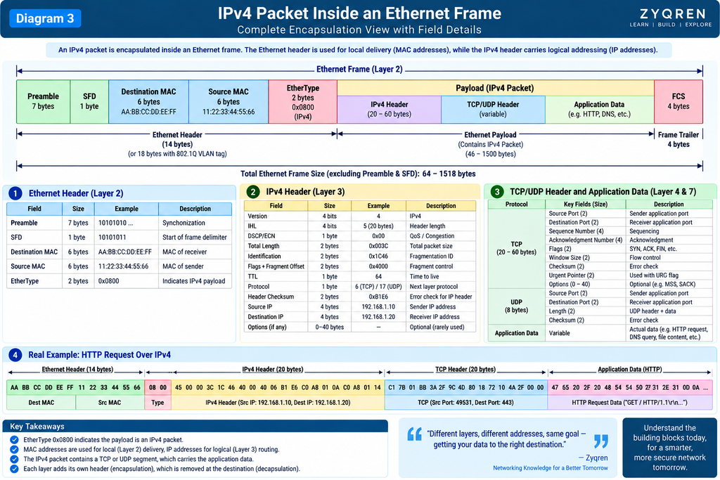
12. IPv4 Inside Ethernet
Suppose PC-A wants to communicate with an IPv4 host.
The IPv4 packet may contain:
Source IP:
192.168.1.10

Destination IP:
192.168.1.20
The Ethernet frame around it may contain:
Source MAC:
00:11:22:33:44:55

Destination MAC:
AA:BB:CC:DD:EE:FF

EtherType:
0x0800
Conceptually:
┌──────────────────────────────────────────────┐
│ Ethernet                                     │
│                                              │
│ Dest MAC = AA:BB:CC:DD:EE:FF                 │
│ Src MAC  = 00:11:22:33:44:55                 │
│ EtherType = 0x0800                           │
│                                              │
│ ┌──────────────────────────────────────────┐ │
│ │ IPv4                                     │ │
│ │                                          │ │
│ │ Src IP  = 192.168.1.10                   │ │
│ │ Dest IP = 192.168.1.20                   │ │
│ │                                          │ │
│ │ TCP/UDP                                  │ │
│ │ Application Data                         │ │
│ └──────────────────────────────────────────┘ │
│                                              │
│ FCS                                          │
└──────────────────────────────────────────────┘
Notice something very important:
MAC addresses and IP addresses perform different jobs.
MAC → Layer-2 local delivery

IP  → Layer-3 logical addressing/routing
13. IPv6 Inside Ethernet
IPv6 works in the same general encapsulation model.
For IPv6:
EtherType = 0x86DD
Conceptually:
Ethernet Frame
│
├── Destination MAC
├── Source MAC
├── EtherType = IPv6
│
└── IPv6 Packet
     │
     ├── IPv6 Header
     ├── TCP/UDP/ICMPv6
     └── Application Data
So It can carry both IPv4 and IPv6 packets.
14. Ethernet Frame vs IP Packet
This distinction should always be clear.
Ethernet
Data unit:
Frame
Uses:
MAC addresses
Works primarily at:
Layer 2
IP
Data unit:
Packet
Uses:
IP addresses
Works at:
Layer 3
Therefore:
Ethernet Frame
└── IP Packet
    └── TCP Segment
        └── Application Data
For UDP:
Ethernet Frame
└── IP Packet
    └── UDP Datagram
        └── Application Data
15. How Does a Switch Know Where to Send the Frame?
This is where the MAC Address Table becomes important.
Imagine:
             Switch
          ┌─────┼─────┐
          │     │     │
         PC-A  PC-B  PC-C
Suppose:
PC-A MAC = AA:AA:AA:AA:AA:AA
PC-B MAC = BB:BB:BB:BB:BB:BB
PC-C MAC = CC:CC:CC:CC:CC:CC
The switch maintains a table such as:
MAC Address              Port
--------------------------------
AA:AA:AA:AA:AA:AA        Port 1
BB:BB:BB:BB:BB:BB        Port 2
CC:CC:CC:CC:CC:CC        Port 3
This is the switch’s MAC address table.
Depending on the switch/vendor, you may also hear terms such as:
- MAC table
- CAM table
- Forwarding database (FDB)
16. How Does the Switch Learn MAC Addresses?
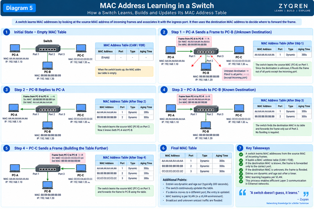
This is one of the most important Ethernet concepts.
Suppose PC-A sends a frame.
The frame arrives at Port 1:
Source MAC = AA:AA:AA:AA:AA:AA
The switch looks at the source MAC.
It learns:
AA:AA:AA:AA:AA:AA → Port 1
Then suppose PC-B replies from Port 2.
The switch learns:
BB:BB:BB:BB:BB:BB → Port 2
The table becomes:
MAC                         Port
----------------------------------
AA:AA:AA:AA:AA:AA           1
BB:BB:BB:BB:BB:BB           2
The switch continually learns and updates these mappings as frames arrive.
In enterprise networks, Ethernet switching is often part of a much larger infrastructure that includes services such as Active Directory for centralized identity and network resource management.
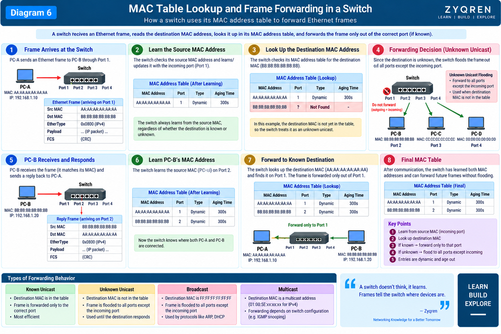
17. The Switch’s Decision Process
Suppose PC-A wants to send a frame to PC-B.
PC-A
  │
  │ Frame
  ▼
Switch
The switch sees:
Source MAC:
AA:AA:AA:AA:AA:AA

Destination MAC:
BB:BB:BB:BB:BB:BB
Step 1
Look at the source MAC.
AA:AA:AA:AA:AA:AA → Port 1
Learn/update it.
Step 2
Look at the destination MAC.
BB:BB:BB:BB:BB:BB
Step 3
Search the MAC table.
BB:BB:BB:BB:BB:BB → Port 2
Step 4
Forward the frame toward Port 2.
PC-A
 │
 ▼
Switch
 │
 │ Port 2
 ▼
PC-B
The switch does not normally send that known unicast frame out every port.
It forwards it based on its forwarding information.
18. What If the Destination MAC Is Unknown?
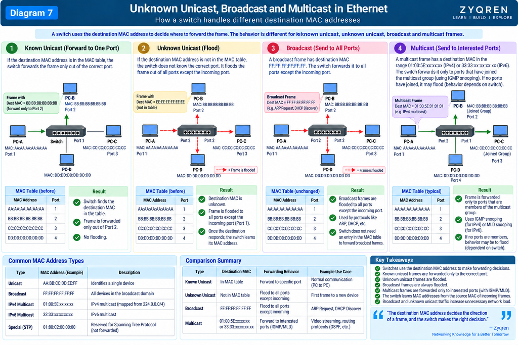
Now imagine the switch receives:
Destination MAC:
DD:DD:DD:DD:DD:DD
but this MAC is not currently in its forwarding table.
The switch cannot determine the specific outgoing port from its table.
For an unknown unicast, the switch generally floods the frame within the relevant Layer-2 domain, except back out the ingress port.
Conceptually:
             Switch
           /    |    \
          /     |     \
        PC-A   PC-B   PC-C
                 ↑
          Frame may be
          flooded here
Once the destination responds, the switch can learn the source MAC of that response and build useful forwarding information.
19. Broadcast MAC Address
It also supports broadcast frames.
The Ethernet broadcast destination address is:
FF:FF:FF:FF:FF:FF
This means the frame is intended for all stations in the relevant Layer-2 broadcast domain.
A classic example is ARP in IPv4 networks.
Conceptually:
PC-A
  │
  │ Broadcast
  │ FF:FF:FF:FF:FF:FF
  ▼
Switch
 ├── PC-B
 ├── PC-C
 └── PC-D
Broadcast behavior becomes particularly important when learning VLANs and broadcast domains.
20. Unicast, Broadcast and Multicast
Ethernet traffic can broadly involve:
Unicast
One sender → one destination.
A ─────────→ B
Broadcast
One sender → all relevant devices in the broadcast domain.
       ┌──→ B
A ─────┼──→ C
       └──→ D
Multicast
One sender → a subscribed/group of receivers.
       ┌──→ B
A ─────┼──→ C
       └──→ D
The forwarding behavior depends on the switch, network configuration, and multicast mechanisms in use.
21. FCS — Frame Check Sequence
At the end of the Ethernet frame is the:
FCS = Frame Check Sequence
It is used for error detection.
The sender calculates a value based on the frame contents, typically using a CRC mechanism, and places the result in the FCS field.
Conceptually:
Frame Data
    ↓
CRC Calculation
    ↓
FCS
The receiver performs its own calculation.
If the received result does not match:
Calculated CRC ≠ Received FCS
the frame is considered corrupted.
The Ethernet interface can then discard the bad frame.
Important:
FCS detects errors; it does not provide encryption or security.
It also does not mean Ethernet retransmits the corrupted frame itself.
22. Why Does FCS Matter?
Imagine electrical or physical interference causes bits to change while travelling across a link.
Original:
101100101010...
Received:
101100001010...
The contents are no longer identical.
FCS helps the receiver detect that the frame was corrupted.
This is one reason packet captures taken at a host may not always show FCS: network adapters and capture systems often handle or strip the Ethernet FCS before software sees the frame.
23. Complete Journey of Data
Now let’s combine everything.
Suppose:
PC-A
IP  = 192.168.1.10
MAC = AA:AA:AA:AA:AA:AA
wants to communicate with:
PC-B
IP  = 192.168.1.20
MAC = BB:BB:BB:BB:BB:BB
The application creates data:
"Hello"
Application Layer
Hello
Transport Layer
TCP/UDP adds its header.
TCP/UDP Header
+
Hello
Network Layer
IPv4 adds its header.
IPv4 Header
+
TCP/UDP Header
+
Hello
Ethernet Layer
Ethernet adds:
Destination MAC
Source MAC
EtherType
And the frame eventually has FCS associated with the transmitted frame.
Conceptually:
┌──────────────────────────────────────────────┐
│ Ethernet                                     │
│                                              │
│ Dest MAC = BB:BB:BB:BB:BB:BB                 │
│ Src MAC  = AA:AA:AA:AA:AA:AA                 │
│ EtherType = IPv4                             │
│                                              │
│ ┌──────────────────────────────────────────┐ │
│ │ IPv4                                     │ │
│ │ Src IP  = 192.168.1.10                   │ │
│ │ Dest IP = 192.168.1.20                   │ │
│ │                                          │ │
│ │ TCP/UDP                                  │ │
│ │ Hello                                    │ │
│ └──────────────────────────────────────────┘ │
│                                              │
│ FCS                                          │
└──────────────────────────────────────────────┘
Then the Ethernet interface converts the frame into physical-layer signaling and transmits it across the link.
24. What Happens at the Receiving Computer?
The reverse process occurs.
PC-B receives the Ethernet frame.
Conceptually:
Physical Signals
       ↓
Ethernet Interface
       ↓
Ethernet Frame
       ↓
FCS Check
       ↓
Destination MAC Processing
       ↓
EtherType Processing
       ↓
IPv4 / IPv6
       ↓
TCP / UDP
       ↓
Application
The receiver effectively unwraps the layers.
This is called decapsulation.
25. Encapsulation vs Decapsulation
Sender
Application Data
      ↓
TCP/UDP
      ↓
IP
      ↓
Ethernet
      ↓
Physical Transmission
This is:
Encapsulation
Receiver
Physical Reception
      ↓
Ethernet
      ↓
IP
      ↓
TCP/UDP
      ↓
Application Data
This is:
Decapsulation
The overall picture:
SENDER                                      RECEIVER

Application                                Application
    │                                           ▲
    ▼                                           │
TCP/UDP                                      TCP/UDP
    │                                           ▲
    ▼                                           │
IPv4/IPv6                                    IPv4/IPv6
    │                                           ▲
    ▼                                           │
Ethernet Frame ─────── Network Link ──────→ Ethernet
    │
    ▼
Physical Signals
26. What Changes and What Doesn’t?
This is a very important concept when understanding switching and routing.
Suppose a frame travels through a Layer-2 switch.
The switch generally forwards the Ethernet frame within the local Layer-2 domain.
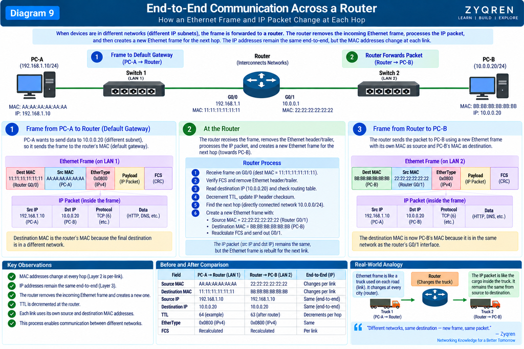
But when a packet crosses a router, the Layer-2 frame is removed and a new Layer-2 frame is created for the next link.
For example:
PC-A
  │
  │ Ethernet Frame #1
  ▼
Switch
  │
  ▼
Router
  │
  │ Ethernet Frame #2
  ▼
Switch
  │
  ▼
PC-B
The IP packet is carried inside a different Layer-2 frame on the next link.
This is why MAC addresses are fundamentally link-local, while IP addresses provide logical addressing across routed networks.
27. MAC Address vs IP Address
A simple way to remember the difference:
| Feature | MAC Address | IP Address |
|---|---|---|
| Layer | Layer 2 | Layer 3 |
| Used by | Ethernet | IP |
| Purpose | Local/link delivery | Logical addressing and routing |
| Example | AA:BB:CC:DD:EE:FF | 192.168.1.10 |
| IPv4/IPv6 | Not dependent on IP version | IPv4 or IPv6 |
| Used by Ethernet switch | Yes | No, not for normal L2 forwarding |
| Used by router | As part of each link’s L2 delivery | Yes |
The most important distinction:
A switch primarily forwards Ethernet frames using MAC addresses. A router forwards IP packets using IP addresses.
28. Where Does ARP Fit?
In an IPv4 Ethernet network, a device may know the destination IP but still need the destination MAC address for local delivery.
For example:
I know:

Destination IP =
192.168.1.20

But I need:

Destination MAC = ?
ARP can be used to discover the IPv4-to-MAC mapping on the local network.
Conceptually:
"Who has 192.168.1.20?"

        ↓

ARP Request
        ↓
Ethernet Broadcast
FF:FF:FF:FF:FF:FF
The device owning that IPv4 address can respond with its MAC address.
IPv6 uses Neighbor Discovery Protocol (NDP) rather than ARP.
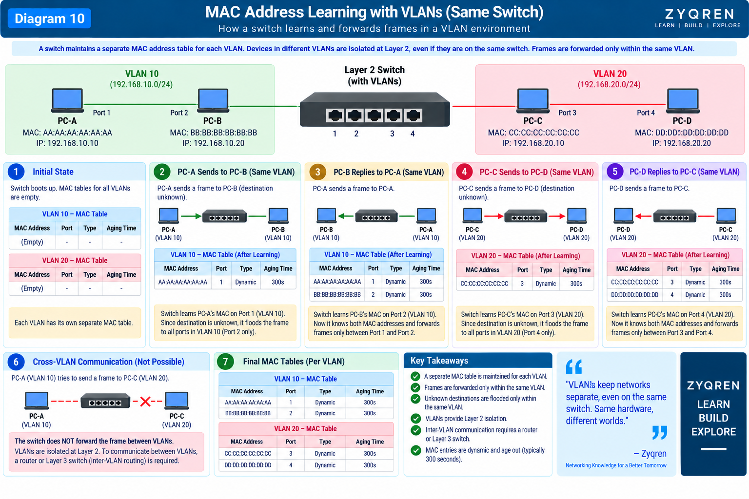
29. Ethernet and VLAN
Once Ethernet frames are understood, VLAN becomes much easier.
An IEEE 802.1Q VLAN tag can be inserted into the Ethernet frame.
Simplified:
Normal Ethernet:

Dest MAC
Src MAC
EtherType
Payload
FCS
802.1Q tagged Ethernet:
Dest MAC
Src MAC
802.1Q VLAN Tag
EtherType
Payload
FCS
The VLAN tag contains a 12-bit VLAN Identifier (VID) along with other fields.
This allows a physical switching infrastructure to carry logically separated Layer-2 networks.
30. Ethernet Frame With VLAN
Conceptually:
┌──────────┬──────────┬──────────┬─────────────┬──────────┬────────|
│ Dest MAC │ Src MAC  │ 802.1Q   │ EtherType   │ Payload  │ FCS    │
│          │          │ Tag      │             │          │        │
└──────────┴──────────┴──────────┴─────────────┴──────────┴────────┘
The VLAN tag is not part of every Ethernet frame.
It appears when the frame is being carried as a VLAN-tagged frame.
This becomes especially important on trunk links.
31. Ethernet MTU and Frame Size
It also has frame-size constraints.
For a traditional Ethernet II frame without an 802.1Q tag:
Destination MAC     6 bytes
Source MAC          6 bytes
EtherType            2 bytes
Payload              typically 46–1500 bytes
FCS                  4 bytes
The resulting frame is normally:
64–1518 bytes
excluding the Preamble and SFD.
With an 802.1Q VLAN tag, the maximum frame size becomes larger by 4 bytes:
64–1522 bytes
Again, these values describe traditional Ethernet framing; modern networks may support larger jumbo frames depending on the equipment and configuration.
32. Minimum Ethernet Frame Size
Traditional Ethernet has a minimum frame size of 64 bytes, excluding the Preamble and SFD.
Why?
Historical Ethernet mechanisms required a sender to remain transmitting long enough for collision detection in classic shared-medium Ethernet.
Modern switched full-duplex Ethernet does not normally use CSMA/CD for collision handling, but the minimum frame size remains part of Ethernet framing requirements.
This is an excellent example of how modern Ethernet retains concepts that originated in earlier Ethernet designs.
33. Ethernet Is More Than Just a Cable
When people say:
“Ethernet”
they sometimes mean only the physical cable.
But understanding network fundamentals such as Ethernet, switching, and Layer-2 communication is also important when studying network security and vulnerabilities in enterprise environments
It includes concepts related to:
Ethernet
├── Frame format
├── MAC addressing
├── Layer-2 forwarding
├── Ethernet interfaces
├── Link speeds
├── Physical media
├── Full-duplex operation
├── VLAN tagging
└── Physical/Link standards
Common Ethernet media include:
Copper
Fiber
Different Ethernet standards support different speeds and physical media.
34. A Complete Mental Model
The easiest way to understand Ethernet is to imagine a delivery system.
Application Data
The actual information:
"Open this webpage"
TCP/UDP
Adds transport information:
Who is the application process?
How should the transport communication work?
IP
Adds logical addressing:
Source IP
Destination IP
Ethernet
Adds local-link addressing:
Source MAC
Destination MAC
Switch
Uses the MAC address table:
Destination MAC
       ↓
Forwarding decision
       ↓
Correct port
Physical Layer
Converts the frame into physical signaling:
Bits
 ↓
Electrical / Optical / Radio signaling
35. The Full Picture
Put everything together:
                APPLICATION
                     │
                     ▼
              Application Data
                     │
                     ▼
                TCP / UDP
                     │
                     ▼
                 IP Packet
             ┌───────┴────────┐
             │ IPv4 / IPv6    │
             └───────┬────────┘
                     │
                     ▼
              Ethernet Frame
       ┌─────────────────────────────┐
       │ Destination MAC             │
       │ Source MAC                  │
       │ 802.1Q Tag (if applicable)  │
       │ EtherType                   │
       │                             │
       │       IP Packet             │
       │       ├─ IP Header          │
       │       ├─ TCP/UDP            │
       │       └─ Application Data   │
       │                             │
       │ FCS                         │
       └─────────────────────────────┘
                     │
                     ▼
              Physical Signaling
                     │
                     ▼
                   CABLE
                     │
                     ▼
                  SWITCH
                     │
              MAC Table Lookup
                     │
                     ▼
              Correct Port
                     │
                     ▼
             Destination Host
36. The Most Important Terms to Remember
Ethernet
The technology used for wired LAN communication and framing/link operation.
Frame
The Layer-2 data unit used by Ethernet.
MAC Address
The Layer-2 address used for Ethernet delivery on a link.
MAC Address Table
The switch’s learned mapping between MAC addresses and forwarding ports.
IP Packet
The Layer-3 data unit carried inside Ethernet when using IP.
IPv4
The 32-bit IP addressing protocol.
Example:
192.168.1.10
IPv6
The 128-bit IP addressing protocol.
Example:
2001:db8::10
EtherType
Identifies the protocol carried in the Ethernet payload.
0x0800 → IPv4
0x86DD → IPv6
0x0806 → ARP
Payload
The data carried inside the Ethernet frame; in an IP network, this can be an IPv4 or IPv6 packet.
Preamble
7-byte synchronization pattern before the frame.
SFD
Start Frame Delimiter; marks the start of the actual Ethernet frame.
FCS
Frame Check Sequence used for detecting transmission errors.
Encapsulation
Adding headers/trailers as data moves down the protocol stack.
Decapsulation
Removing/processing those protocol layers as data moves up the stack at the receiver.
37. One-Line Memory Trick
Remember the complete flow like this:
APPLICATION DATA
       ↓
TCP / UDP
       ↓
IPv4 / IPv6 PACKET
       ↓
ETHERNET FRAME
       ↓
MAC ADDRESS
       ↓
SWITCH MAC TABLE
       ↓
CORRECT PORT
       ↓
PHYSICAL SIGNAL
       ↓
DESTINATION
Or even more simply:
Data becomes a packet, the packet becomes the payload of a frame, the frame is forwarded using MAC information, and the frame is finally transmitted as physical signals.
Conclusion
Ethernet is the foundation on which a huge portion of modern networking is built.
To understand Ethernet properly, you should not memorize only the frame diagram:
Preamble | SFD | Destination MAC | Source MAC |
EtherType | Payload | FCS
You should understand why every field exists and what happens to the frame as it moves through the network.
A device generates application data. Transport protocols add their information. IPv4 or IPv6 creates an IP packet. Ethernet places that packet inside a Layer-2 frame and adds source and destination MAC addresses. A switch examines the destination MAC and consults its MAC address table to make a forwarding decision. The frame is then transmitted over the physical medium. At the receiving device, the frame is checked, processed, and decapsulated until the original application data reaches its destination.